In Flutter’s legacy renderer, an animation could stutter on its first run and play smoothly on its second. Sometimes the difference was a shader: the engine encountered a drawing combination it hadn’t used before, and preparing its GPU program delayed the frame. Dart could finish on time and the animation could still miss a refresh.
Impeller gives Flutter a known set of built-in shaders to process ahead of time. That removes an important source of first-use uncertainty, but it doesn’t finish the frame’s work in advance. The driver still has pipelines to prepare. The scene still needs geometry, glyphs, and, for some effects, intermediate images.
To see where those boundaries fall, take a rounded panel with a gradient and text. Put its contents inside a clip, blur the background behind it, then fade the group. Each addition asks something different of the renderer. The gradient needs changing colors, the clip needs a restriction that survives later draws, and the blur needs pixels the renderer has already produced.
Why Flutter built Impeller
Flutter paints ordinary widgets through its own rendering stack. The framework builds and lays out the interface, then records drawing operations for the engine. Impeller sits below those stages and turns the recorded operations into pixels. Flutter’s architectural overview places this work within the engine’s rendering stack.
That arrangement lets applications combine custom paths, gradients, clips, text, and filters without handing each widget to a native control. It also means the renderer must handle combinations that appear while the application is running, including screens nobody exercised during development.
Shader warmup tried to prepare the legacy rendering path before users reached those interactions. Developers could exercise common operations at startup, supply custom warmup, or capture SkSL shaders during a training run and package them for later preparation. The approach helped when the captured work covered what the application eventually drew.
But how would a training run cover an authenticated screen, an input-dependent effect, or a drawing combination added in the next release? Increasing warmup coverage also increased startup work. A delay moved before the first screen still had to be paid. Flutter’s Impeller FAQ explains why an engine-controlled shader set offered a better basis for preparation.
At 60 Hz, refreshes are about 16.67 ms apart; at 120 Hz, about 8.33 ms. Dart execution, rendering, and presentation overlap, so these aren’t separate budgets for each stage. Once a frame misses its refresh, fast frames later can’t recover it. A first route transition can matter more to the experience than its few frames suggest in a long performance trace.
With Impeller, the engine defines the built-in drawing programs, and applications supply the shapes and effect parameters they consume. Preparation depends less on whether somebody visited the right screen. Understanding the rest of the design means asking which changes can become program inputs and which require work on the device.
Preparing shaders and pipelines
Our panel can move, resize, or change color throughout an animation. Those changes don’t all require a different GPU program. The program that evaluates a gradient and the data describing this particular gradient have different lifetimes.
A gradient as data
Moving the panel changes a transform. Resizing it changes geometry. Replacing two colors with five changes the gradient’s input records. The program can remain fixed while the panel changes every frame.
One of Impeller’s gradient shaders makes that separation explicit. Notice that the stops arrive in a buffer; the shader source doesn’t embed a particular set of colors:
struct ColorPoint {
  vec4 color;
  float stop;
  float inverse_delta;
};

layout(std140) readonly buffer ColorData {
  ColorPoint colors[];
}
color_data;
A separate uniform supplies the stop count. For each fragment, the program projects its position along the gradient, applies the tiling behavior, finds the surrounding stops, and interpolates their colors. Changing the stops replaces the records supplied to that calculation.
This is one storage-buffer implementation, rather than a promise that every backend uses the same data layout. The useful distinction is between the program and its inputs. Impeller’s color-source code binds those inputs and selects the draw’s pipeline state. The same gradient calculation can color several shapes because it doesn’t have to implement each shape’s boundary.
The CPU needs to agree with the shader about the layout of those buffers. Impeller’s compiler derives reflected interfaces and host bindings from the processed programs. CPU code fills a generated FrameInfo structure and binds it through BindFrameInfo, using the layout derived from the shader interface.
So an animated gradient doesn’t need a newly generated color program for each intermediate position. More stops can still mean more data and shader work. And the gradient hasn’t answered which samples belong to the panel. The renderer must also prepare its boundary.
Pipelines on the device
Before following that boundary, there’s another preparation stage to separate from shader processing. A shader program isn’t a complete graphics pipeline.
Impeller’s compiler uses SPIR-V as an intermediate representation and produces backend artifacts ahead of time. On the device, the driver must turn the relevant artifacts and draw state into a usable pipeline or linked program. Attachment formats, sample count, blending, and depth or stencil behavior can require different variants, even when the gradient calculation stays the same.
Impeller’s ContentContext organizes those combinations, prepares common defaults asynchronously, and obtains variants as they’re requested. Metal creates render-pipeline states through Apple’s API; Vulkan creates graphics pipelines using a driver cache. The GLES backend still calls the driver to compile shaders and link programs at runtime. Processing source offline and completing driver preparation are separate events.
If the panel needs a pipeline that isn’t ready, the frame can wait. Background preparation creates a scheduling problem too: a needed pipeline shouldn’t sit behind unrelated jobs. The compile queue lets the waiting thread take that pipeline’s pending job and execute it itself. This avoids waiting for the queue to reach it, although the preparation itself still takes time. Vulkan cache reuse can reduce repeated driver work, depending on the device, driver, and cache state.
Application fragment shaders have their own build and loading lifecycle. They aren’t automatically part of the engine’s known built-in library. The preparation described here concerns Impeller’s built-in rendering programs, not every program an application might use.
From a DisplayList to GPU draws
Flutter records the panel’s drawing operations in a DisplayList. Impeller needs both the resources those operations will use and the commands that draw them. In the inspected RenderToTarget path, it handles those jobs in two traversals.
The first, through FirstPassDispatcher, collects text frames for glyph-atlas preparation and information about backdrops. The second, through CanvasDlDispatcher, sends rendering operations to Canvas. These traversals inspect recorded drawing operations; they don’t build or redraw the widgets twice.
The panel’s text uses a glyph atlas, a texture containing glyph images that draws address with textured geometry. Gathering requirements first lets atlas preparation see the text about to be drawn. A previously unseen glyph can still require rasterization, packing, and uploading. This is another form of first-use work even when its drawing program is ready. The inspected typographer backend uses Skia to rasterize glyphs, so Skia remains involved in that part of the engine.
Canvas connects each operation to geometry and content that evaluates its color or effect. Those objects bind inputs, select a pipeline, and record draws against a render pass. A pass groups work targeting attachments such as the color image and depth or stencil storage, and specifies what happens to them when the pass begins and ends.
For our panel, the background must be drawn before the backdrop can sample it; the panel’s foreground and text follow the backdrop composition. We’ll examine coverage and clipping together to understand their shared state, rather than treating the section order as a literal command trace. Their attachment lifetime becomes important when blur interrupts the pass.
Path coverage and clipping
The gradient can calculate a color at any position. Impeller still needs to decide whether that position lies inside the panel. A rounded rectangle may take a specialized primitive route, but replacing its outline with curves, holes, or overlapping contours exposes the general path-filling problem.
Stencil then cover
One approach is to flatten the curves into segments, triangulate the interior on the CPU, and shade the resulting triangles. Complex contours make that interior decomposition harder. Having the color program ready doesn’t help the CPU find a suitable triangulation.
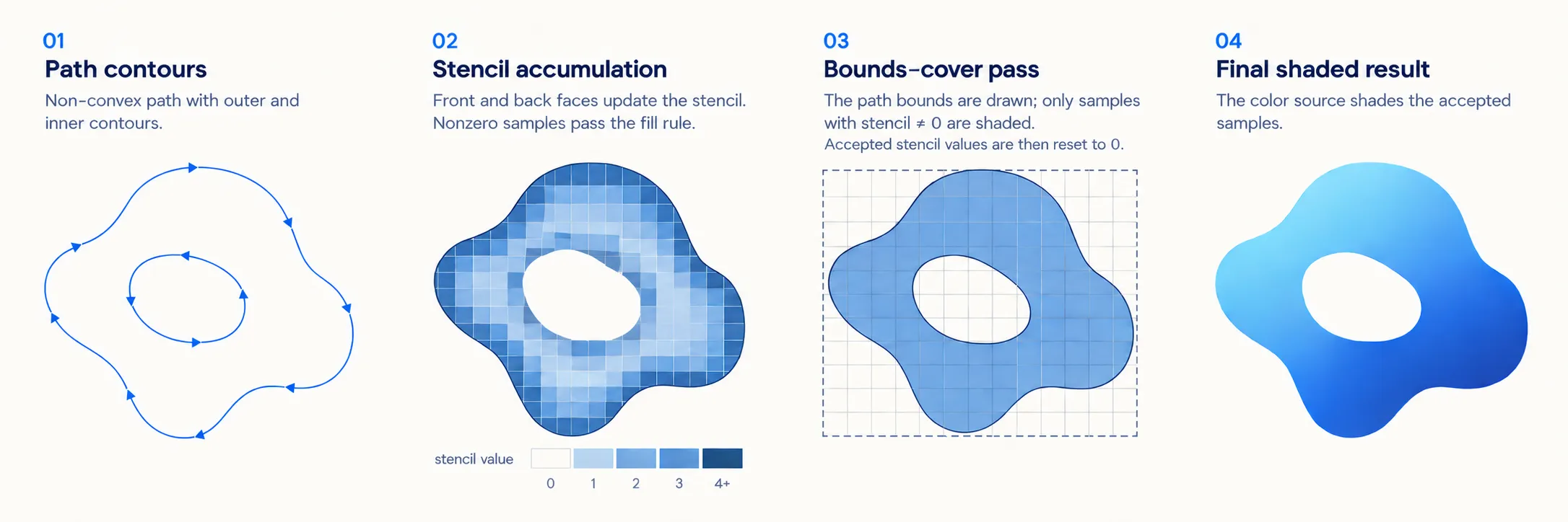
For eligible complex fills, Impeller uses stencil then cover. It still prepares geometry, but lets GPU stencil operations resolve which samples satisfy the fill rule. Stencil is per-sample storage that rasterization can test and update.
The first draw writes stencil without changing the color image. Under the nonzero fill rule, front and back faces increment and decrement the stored value. Contributions that cancel leave a sample outside the fill; a nonzero result marks it as covered. For even-odd filling, the configured operations track parity instead. Neither step needs the gradient calculation.
Consider two nested contours. With the same winding direction, a sample inside both has a nonzero winding count and remains filled under the nonzero rule. Reverse the inner contour and its contribution cancels the outer contour, making a hole. Under even-odd filling, crossing both contours produces an even count, so the inner region is a hole regardless of direction.
The second draw covers the path’s bounds. Its stencil test accepts covered samples, applies the color source there, and resets the relevant stencil values. Stencil determines where; the gradient determines the color. The two draws keep fill-rule handling separate from shading. Convex paths can take a simpler route that avoids the stencil preparation draw.
Curves still need subdivision, and the transform affects how much. A curve that looks smooth at one size can look angular when enlarged. Impeller’s fill geometry supplies the transform’s maximum basis length to the tessellator, so zooming can change the vertices even when the original path and gradient remain unchanged. Strokes also need geometry for caps and joins.
Analytic coverage for simple shapes
For compatible primitives, Impeller can calculate coverage in the fragment shader instead of generating a curved outline. Its signed-distance route evaluates distance to the boundary. For a circle, that is distance from the center minus the radius; values near zero locate the edge and can produce partial coverage for anti-aliasing. Rounded rectangles have their own expression.
This saves some CPU geometry work by doing more fragment work across the enclosing region, including outside the final shape. Canvas selects the route when the configuration and paint are compatible. An arbitrary path has no corresponding primitive formula, so the general path machinery remains necessary.
Storing clips in depth
Filling the panel and clipping its children need state with different lifetimes. A fill uses stencil as temporary scratch space and clears it afterward. The clip must keep restricting later draws. If both live in stencil, clearing a subsequent fill can destroy the restriction it was meant to obey.
Impeller’s depth-based clipping puts that lasting restriction in depth storage. Although depth is familiar from 3D visibility, a 2D renderer can assign values and comparisons that encode which draws are allowed at each sample. An intersect clip excludes the area outside its shape; a difference clip excludes the interior.
Complex clips can still use stencil during construction. Once stencil identifies the shape, an intersect clip uses an inverted comparison to write depth outside it. A difference clip writes depth inside the region being removed. The clip implementation leaves the persistent restriction in depth, freeing stencil for later path fills.
Later draws must agree with the clip about that depth ordering. Otherwise a correctly positioned boundary can reject valid pixels or let drawing escape. Even the floating-point spacing matters: ClipContents takes the encoded depth of the next logical slice and calls std::nextafterf toward zero. That chooses the adjacent representable value on the current slice’s side of the boundary.
The clip must cull draws assigned to that slice even when they have perspective transforms. Placing it at the slice’s upper end preserves that relationship, as the source comment explains. The tiny adjustment protects a visibility rule; treating it as an arbitrary epsilon would miss why it’s there.
While drawing stays in the same pass, the attachment holds this restriction. Adding a backdrop blur raises the next question: what happens to the clip when the renderer leaves that pass?
Backdrop blur and compositing
A backdrop blur samples pixels drawn before the panel. Blurring the panel’s own contents would have a different input. Here, the renderer needs an image of the background, including neighboring pixels that contribute to the blur.
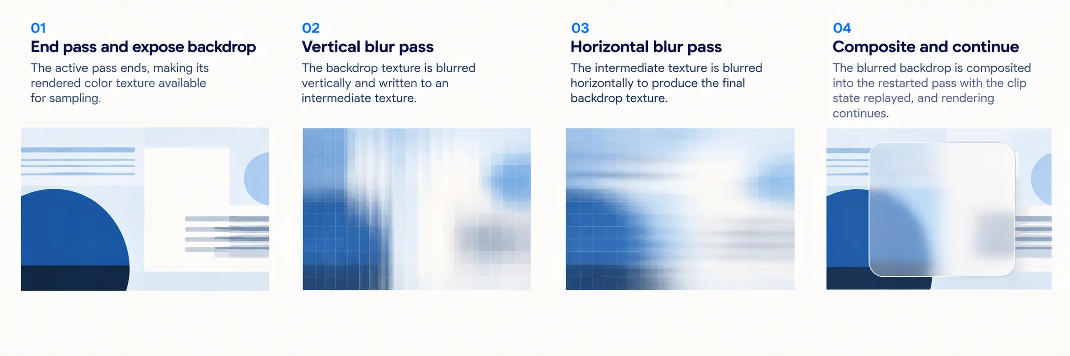
In the inspected Canvas path, obtaining that input can end the active pass and expose its color texture for sampling. Filtering produces the backdrop that will sit behind the panel’s foreground, and drawing continues in a new pass.
The blur passes
The general Gaussian-blur path computes the effective blur under the transform, adds input padding, and can downsample before applying directional passes. Because a Gaussian is separable, the renderer can blur along one axis and then the other. For a simplified kernel with k samples on each axis, that replaces roughly k² samples per output pixel with 2k. It reduces sampling work, while still requiring texture reads, target writes, and pass setup.
Downsampling also reduces the pixels processed by a large blur. Restricting its bounds can save more work, but a pixel near the panel’s edge may depend on source pixels outside the visible output. Cropping the input to that output region would change the result. The input therefore needs padding for the filter’s reach. Specialized primitive blurs may use a different route.
Some advanced blends need previously drawn pixels too, but with a different access pattern. On a suitable backend, framebuffer fetch lets a blend read the destination color at the current fragment’s location without ending the pass for that read. The blur needs neighboring pixels from a texture, so framebuffer fetch can’t supply its input. Impeller’s blending documentation distinguishes the destination-fetch and texture-based routes.
Replaying clips after a pass split
The backdrop’s image is available, but the old clip attachment doesn’t have to survive with it. The renderer can preserve the attachment or retain enough information to reconstruct the restriction in the next pass.
On a tile-based GPU, attachment data can stay in fast tile storage during a pass. Keeping it across a boundary can require stores and later loads, with multisampling increasing the per-sample state involved. Reconstructing a clip may cost less bandwidth than preserving a large attachment. The trade depends on the hardware, backend, and work being drawn.
Impeller’s clip stack retains the logical entries. When a pass restarts, Canvas restores the scissor and replays the necessary clips into its attachments, expressing their transforms in the new pass’s coordinate system. The CPU description survives even when the previous attachment contents are discarded.
The pass-transition code makes a related trade for color: it can redraw the previous pass’s resolved image into a new multisampled target instead of storing and reloading the old multisampled attachment. Resolving combines samples into one color per pixel. Retaining that image and retaining all the old sample values require different amounts of state.
Replay must recover more than the outline. Omitting a parent clip lets drawing escape; a wrong transform moves the boundary; inconsistent depth values reject the wrong samples. The retained entries, pass coordinates, and depth ordering together describe the restriction later draws must obey.
Group opacity and intermediate layers
Now fade the panel’s children together at 50 percent opacity. Applying alpha 0.5 to every draw seems like a way to avoid an intermediate layer, until the children overlap.
Take two opaque shapes. Render them into a group at full opacity, then attenuate the completed group: the overlap has alpha 0.5. Give each child alpha 0.5 and blend them directly with source-over: the overlap has alpha 0.5 + 0.5 × (1 - 0.5), or 0.75. The color can differ too.
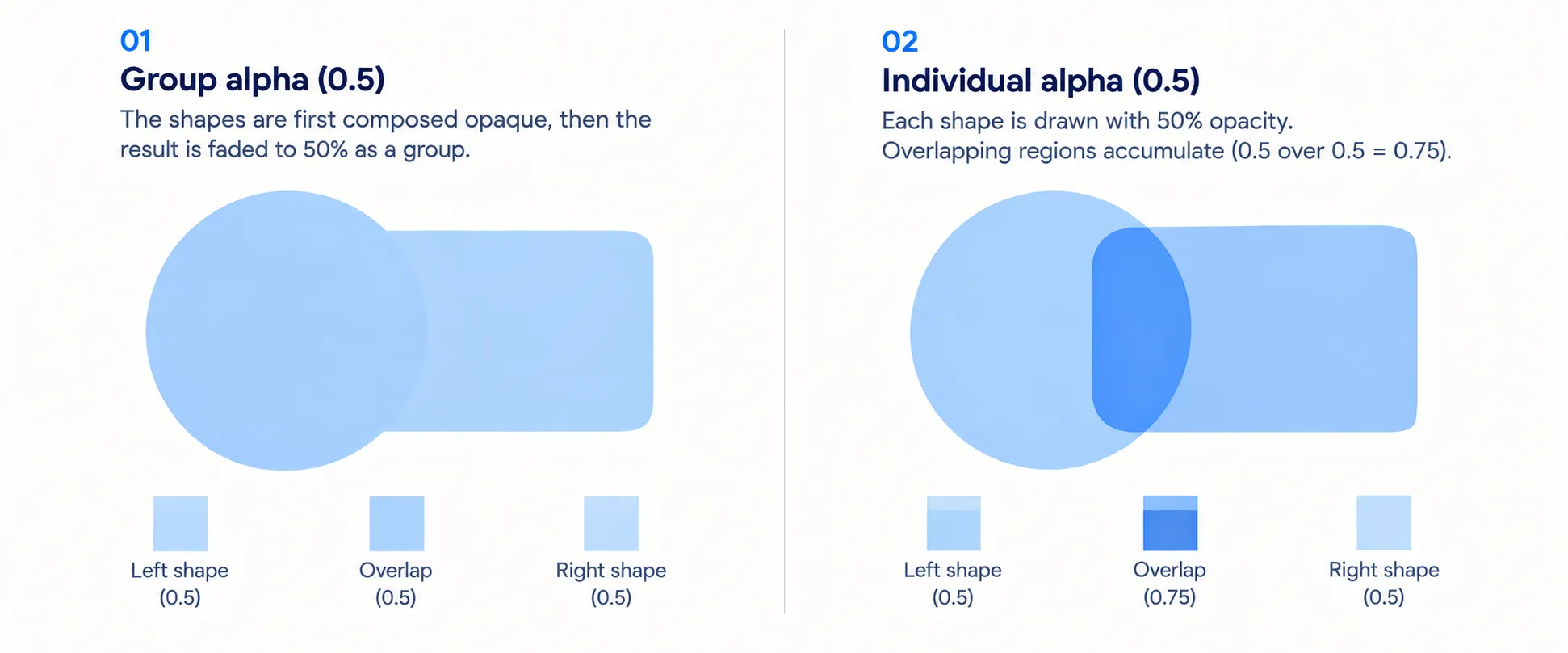
SaveLayer preserves the grouping needed for such operations. Impeller can distribute opacity when recorded information and paint conditions establish that the image will stay the same. Where they don’t, the drawing semantics can require an intermediate layer.
Filtering has the same ordering problem. Filtering the completed group can mix pixels contributed by several children. Filtering each child first and then combining them need not produce the same image. The renderer must preserve where the operation occurs in the composition.
Layer bounds follow that rule too. Blur input can extend beyond visible output; a color filter can change transparent black; some blend modes affect the destination beyond ordinary source coverage. ComputeSaveLayerCoverage accounts for these cases when choosing the region to process. A smaller target is a valid optimization only if its omitted pixels can’t affect the result.
GPU resource lifetimes
The panel’s transforms, gradient records, vertices, and indices need GPU-visible memory. HostBuffer places aligned regions within larger blocks instead of allocating separately for every small record. RenderTargetCache can reuse suitable intermediate-target allocations, although drawing the blur into a reused texture still requires rendering its contents.
Those resources can remain in use after the CPU finishes recording. If the renderer immediately recycled their bytes, it could change inputs the GPU was still reading. Completion tracking and deferred collection allow reuse after the submitted work finishes; the Vulkan threading design gives completion and collection their own handling.
The panel has therefore created dependencies that extend beyond command preparation. Measuring only that preparation would leave part of its cost out of the account.
What to measure on the first frame
A slow raster frame isn’t a diagnosis. The panel has given us several possible causes, and each calls for a different investigation.
Measure startup to first presentation, the first encounter with a scene, and repeated warm rendering separately. A warm median doesn’t tell us whether the first encounter was cheap. Keep cache conditions explicit too: a second launch may reuse driver preparation, while repeated text may already have its glyphs in an atlas. Warming one renderer and leaving the other cold measures that difference along with the renderer.
The panel provides a manageable experiment. Begin with the gradient and text, add the clip, then compare a primitive shadow, a general blur, and a backdrop blur separately. Record CPU preparation, GPU work, and presentation on the same backend and device. Each addition gives a new source of work to look for in the trace.
These timings describe different events. The CPU can finish preparing commands before the GPU completes them; neither event is the moment the frame reaches the display. Compositor backpressure can also delay the raster workload. An improvement in CPU raster time alone doesn’t establish the same improvement in interaction latency.
A pipeline wait points toward device preparation. Atlas work points toward new text. More vertices can follow a transformed path. A backdrop can introduce intermediate images, pass boundaries, and clip replay. Treating all of those as shader compilation would hide the operation responsible for the delay.
Impeller makes the built-in programs available for preparation without discovering every drawing combination through an application. Following the panel shows where the scene still determines the work. A useful trace identifies the pipeline, glyph, geometry, or image dependency that made the frame late.
Implementation notes and sources
Flutter source links in this article point to commit 086a6c853e9034e7b71db12b1b46f558a899aba6, which is the revision I used while tracing the implementation. I checked the relevant paths again on 2 October 2026. Platform behavior and released versions can differ from this snapshot.
The panel above is a worked example. Its blur and alpha values are illustrative rather than device measurements, and I did not run benchmarks for this article.
For the history behind Impeller, see the early shader-jank report, the SkSL capture proposal, and the discussion around the startup cost of shader warmup. The Skia comparison here refers specifically to Flutter’s legacy Skia renderer. Skia Graphite has its own precompilation API, so I have kept that separate from the comparison.
For readers who want to follow the implementation directly, the most relevant paths cover Vulkan pipeline caching, glyph-atlas preparation, text drawing, stroke geometry, curve tessellation, and render-pass attachment handling. The gradient excerpt is from Flutter Authors source under its BSD-style license.